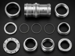
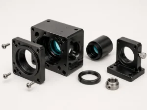
When an optical system fails in the field, the root cause is rarely the lens or sensor itself — it’s almost always a mechanical flaw: misaligned threads causing tilt, light leaks from poor sealing, thermal expansion warping the housing, or a bracket vibrating out of calibration.
At Joint Precision, we’ve seen it all. In this guide, we break down the most common design pitfalls in optical components, and how our CNC machining and DFM process fixes them before you ever build a prototype.
1. The Silent Killer: Misalignment & Poor Concentricity
The Problem
Even a 0.01mm offset in a lens barrel’s thread pitch or a housing’s mounting hole can cause:
- 1–3° of lens tilt, resulting in uneven sharpness across the frame
- Reduced contrast and increased flare from unintended light paths
- Permanent calibration drift in high-precision systems like LiDAR or industrial vision
Our CNC Solution
- Single-setup 5-axis machining: Lens barrels, camera housings, and mounts are machined in one fixture, eliminating alignment errors from multiple setups.
- Tight tolerance control: Thread pitch, concentricity, and runout are held to ±0.005mm, verified with CMM inspection on every batch.
- Thread optimization: We use precision single-point turning for internal/external threads (instead of tapping) to ensure perfect alignment, even on custom pitch profiles.
2. Light Leaks & Stray Reflections: Designing for Optical Integrity
The Problem
Many engineers treat “light tightness” as an afterthought — but gaps between mating surfaces, rough internal finishes, or uncoated aluminum surfaces can cause stray light to bounce into the sensor, washing out contrast and creating ghost images.
Our CNC & Surface Treatment Fix
- Ra ≤ 0.2μm internal finishes: Machined with controlled tool paths to eliminate micro-scratches that cause diffuse reflections.
- Black hard anodization with anti-reflective (AR) topcoats: Not just cosmetic — this treatment absorbs 95%+ of stray light, even on complex internal geometries.
- Integrated sealing grooves: We machine precision O-ring or gasket seats directly into mating surfaces, ensuring a consistent, light-tight fit without relying on secondary assembly shims.
3. Thermal & Mechanical Stability: Designing for Real-World Conditions
The Problem
Optical systems are often used in extreme environments: automotive ADAS sees -40°C to +85°C swings, industrial cameras face constant vibration, and outdoor equipment deals with humidity and temperature cycling. Standard aluminum parts can warp, expand, or loosen over time, throwing off alignment.

- Stress-relieved blanks: All raw material is pre-stress-relieved before machining to eliminate post-production warping.
- Thermal expansion matching: For multi-material assemblies, we adjust part geometries to compensate for different expansion rates, ensuring alignment stays true across temperature ranges.
- Vibration-resistant features: We machine integrated locking threads, serrated mating surfaces, and reinforced mounting points to prevent loosening under constant vibration.
4. DFM Best Practices for Optical Components: From CAD to CNC
Our engineering team reviews every design before machining, and these are the most impactful optimizations we recommend:
- Avoid deep, blind internal features: They trap chips, cause uneven finishes, and increase the risk of light leaks. If possible, add vent holes or split the design into two mating parts.
- Standardize thread profiles where possible: Custom thread pitches require special tooling and increase lead times. We’ll suggest compatible standard profiles (like M42, M48, or C-mount) that still meet your performance needs.
- Add alignment features, not just fasteners: A single precision dowel pin is far more reliable than multiple screws for maintaining concentricity. We’ll integrate these into your design without adding complexity.
- Leave material for post-machining treatments: Black anodization adds ~5–15μm of material, so we adjust critical dimensions (like lens seats) to account for this during machining.
5. Prototype to Production: No Compromises, No Surprises
We know optical projects move fast, and you need to trust that your prototype will translate seamlessly to production. That’s why our process is built for consistency:
- The same CNC programs and tooling are used for prototypes and production runs.
- CMM inspection reports are provided for every prototype, with full traceability for critical dimensions.
- Surface treatments are validated on test coupons before full production, ensuring they meet your optical performance requirements.
At Joint Precision, we’re solving the mechanical problems that sink optical designs. Whether you’re building a new camera system, LiDAR sensor, or industrial vision tool, we partner with you from the first CAD review to the final production run, ensuring your design performs as well in the field as it does on paper.
If you’re ready to build optical components that won’t fail when it matters most, let’s dive into your design and see how we can optimize it for CNC machining.