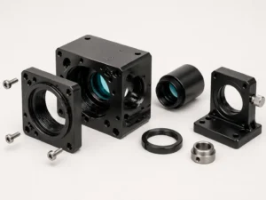
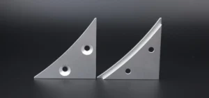
In optical engineering, individual lenses and glass elements never work alone. They are integrated into a complete optical assembly, where every single part requires precise positioning, accurate alignment and stable fixation.
For engineers designing cameras, laser systems, medical imaging devices, machine vision equipment and scientific instruments, optical assemblies are the convergence point of mechanical and optical precision. Even one poorly machined housing or out-of-tolerance lens barrel can misalign the entire optical train, triggering degraded imaging quality, wavefront errors or total system failure.
This post covers what optical assemblies are, their manufacturing workflow, stringent precision standards, and how to pick a machining partner supporting your whole project from prototype validation to stable mass production.
What Is an Optical Assembly?
An optical assembly is an integrated combination of optical glass elements and mechanical structures, designed to collect, guide, focus, filter or detect light.
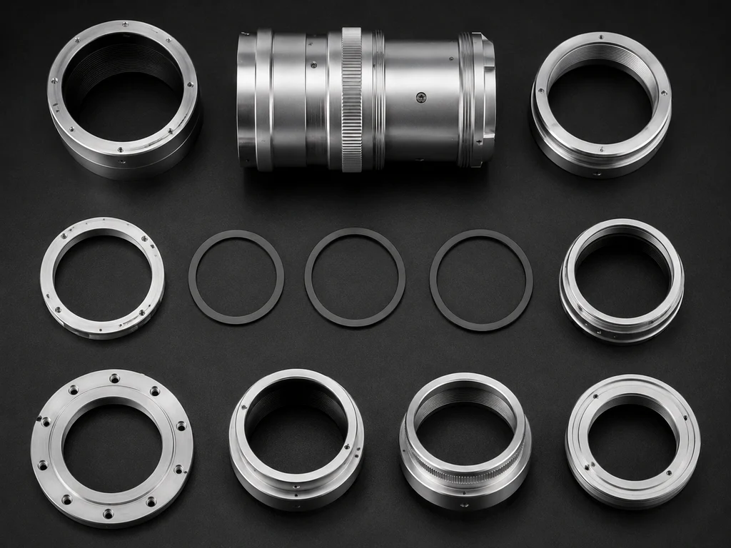
Different from standalone lenses or mirrors, it integrates lens barrels, retaining rings, spacers, mounting flanges and positioning frames into one fully functional unit.
Typical application scenarios
Industrial machine vision | Laser processing heads | Medical endoscopes & imaging modules
Surveillance & defense optics | Semiconductor inspection equipment | Laboratory scientific instruments
Glass quality alone cannot guarantee stable optical performance. The mechanical components holding and aligning optical elements are equally critical. Out-of-round barrels, uneven flange surfaces or spacer thickness deviations will ruin overall optical performance, even with flawless glass lenses.
Core Mechanical Components of Precision Optical Assemblies
- Lens Barrels Main structural housing to locate optical elements along the optical axis; tight bore tolerance, controlled roundness and accurate thread angle are mandatory. Coaxiality between segmented barrels is decisive for multi-lens groups.
- Retaining & Threaded Rings Lock lenses in position without stress or tilt; thread profile, flatness and perpendicularity to the optical axis must be strictly controlled.
- Spacers & Shims Define air gaps between lenses; thickness tolerance directly changes back focal length and optical path. A 5–10 μm thickness error will severely affect high-precision systems.
- Mounting Flanges & Interfaces Connect the assembly to main equipment; flatness, parallelism and hole positioning accuracy determine final system alignment stability.
- Focus & Zoom Adjustment Structures Require consistent thread pitch, smooth travel and repeatable positioning without backlash or tilting.
Precise machining of individual parts is insufficient. Optical assembly manufacturing is a systematic engineering challenge rather than simple dimensional control.
How Mechanical Precision Determines Optical Performance
A tolerance of ±0.05 mm is rigorous for ordinary machinery, yet inadequate for optical assemblies.
Optical systems are extremely sensitive to tiny positional deviations:
- A 0.01° lens tilt introduces coma or astigmatism
- A 10 μm lens offset reduces resolution and image contrast
- Uneven barrel bore roundness squeezes lenses and deforms glass optics
For critical features in high-end optical assemblies, mechanical tolerances are tightened to ±1–5 μm. Inner bore surface roughness needs Ra ≤ 0.1–0.4 μm to suppress stray light and ensure seamless lens fitting.
Optical machining demands specialized equipment, mature processes and complete inspection systems, plus deep understanding of how tolerances influence real optical performance.
| Component | Typical Critical Tolerance | Key Impact |
|---|---|---|
| Lens barrel inner bore | ±1–5 μm | Lens fitting accuracy & focusing stability |
| Spacer thickness | ±2–10 μm | Back focal length & optical path design |
| Flange flatness | ≤ 2–5 μm | Installation tilt & system alignment |
| Thread pitch & profile | Standard precision control | Smooth focusing & repeatable positioning |
| Barrel coaxiality | ≤ 3–10 μm | Consistent optical axis across all elements |
| Inner surface roughness | Ra ≤ 0.1–0.4 μm | Stray light suppression & clean lens seating |
CNC Machining Workflow for Optical Assembly Parts
Most mechanical optical structures are produced via precision CNC machining, selected based on geometry, tolerance and batch volume:
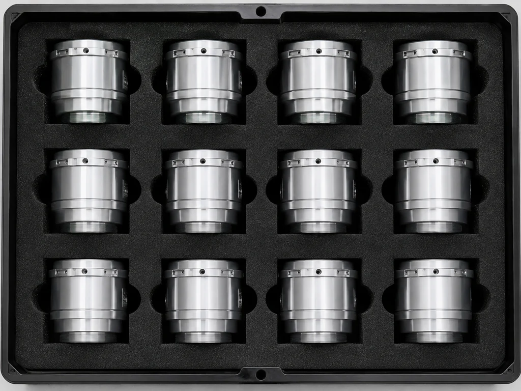
- CNC Turning: Primary process for circular parts (barrels, rings, shims, sleeves). Outer & inner bores are machined in one setup to guarantee high coaxiality.
- CNC Milling: For flanges, mounting brackets, housings with pockets and multi-hole layouts; multi-axis milling handles complex angled integrated features.
- 5-Axis CNC Machining: Consolidates multiple functional surfaces into one single fixture setup, eliminates accumulated positioning errors, ideal for ultra-precision optical components.
- Secondary processes: Thread grinding, honing and precision reaming for ultra-tight tolerance bores and fine-pitch threads.
Material Selection for Optical Assemblies
| Material | Advantages & Application Notes |
|---|---|
| 6061 / 7075 Aluminum | Most widely used; balanced machinability, lightweight and thermal conductivity. Black anodization blocks stray light. Higher CTE requires temperature compensation for wide working temperature ranges. |
| Stainless Steel | High strength & corrosion resistance; adopted for medical optics with sterilization requirements and biocompatibility demands. |
| Titanium Alloy | Low CTE + excellent strength-to-weight ratio; used in aerospace & defense optical assemblies needing long-term dimensional stability. |
| Invar / Super Invar | Ultra-low thermal expansion coefficient; the top choice for space instruments and high-precision metrology optical systems. |
Material selection shall be finalized in early design phase; late material replacement will alter tolerance scheme, surface treatment options and production lead time.
Surface Finish & Coating Requirements
- Inner barrel surfaces need low roughness to avoid particle accumulation and stray light scattering. Black anodization or matte black coating is standard for aluminum barrels to cut internal reflection.
- Lens seating surfaces must be perfectly flat and burr-free; uneven spots will tilt lenses when retaining rings are tightened.
- Anodization adds 5–25 μm material thickness per side; extra machining allowance must be reserved for tight-tolerance bores in advance.
Key Challenges: Alignment, Focusing & System Integration
Perfectly machined individual parts do not guarantee qualified finished assemblies:
- Active alignment: Real-time optical testing during assembly for ultra-high-precision products to correct eccentricity and tilt.
- Passive alignment: Relies on ultra-rigorous mechanical tolerances and benchmark surfaces for consistent positioning.
- Stray light suppression: Optimized internal coatings, baffles, aperture stops and thread profiles eliminate unwanted internal reflection.
Quality Control & Inspection Standards
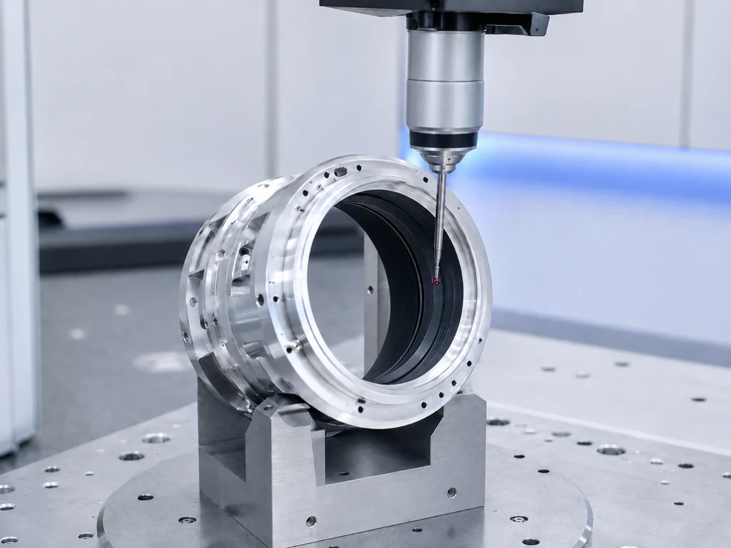
- CMM coordinate measuring machine: Tests bore dimension, roundness, flatness, coaxiality and hole positions.
- Profilometer: Verifies surface roughness of critical fitting surfaces.
- Thread gauges & CMM scanning: Inspects precision optical threads.
- Medical optical assemblies: Full ISO 13485 traceable process control and complete FAIR first article inspection documents.
A reliable optical machining supplier can customize inspection plans for CTQ features and deliver full QC documentation to match your internal quality system.
From Prototype Verification to Mass Production
- Prototype Stage: Rapid turnaround, flexible design revisions and close technical communication. DFM review optimizes hard-to-machine features, over-tight tolerances and surface treatment allowances upfront.
- Mass Production Stage: Focus on process stability, batch repeatability and cost optimization.
Working with one supplier covering both prototyping and volume production avoids technical handover risks and accelerates project iteration.
Why Choose Joint Precision for Custom Optical Assemblies
We deliver full-set precision CNC machining services for optical assemblies, including lens barrels, housings, spacers, retaining rings, flanges and custom optomechanical structures.
✅ Equipped with CNC turning, milling and 5-axis machining centers
✅ Minimum tolerance up to ±1 μm, surface roughness down to Ra ≤ 0.1 μm
✅ ISO 9001 & ISO 13485 certified; serves machine vision, medical imaging, aerospace and scientific instrument clients
✅ Full DFM analysis, in-process checkpoint inspection and complete final dimensional reports
✅ Supports black/hard anodizing, passivation, bead blasting and other customized surface treatments
✅ Seamless support from single prototype trial to stable batch production
FAQ Quick Reference
- How tight are your achievable tolerances? Critical bores and lens seats reach ±1 μm, Ra ≤0.1 μm. Feasibility evaluation is provided for every drawing before production.
- What materials are commonly used for optical housings? 6061/7075 aluminum for general use; stainless steel for medical corrosive environments; titanium & Invar for low thermal expansion requirements.
- Can you provide black anodization for stray light reduction? Yes. We confirm coating thickness allowance via DFM review to avoid dimensional interference for precision fitting features.
- Are full inspection records available? We supply CMM reports, roughness test data and FAIR documents; full material traceability for ISO 13485 medical projects.
- What is your MOQ? No minimum order quantity for prototype samples; flexible batch support for volume orders.
Closing Remarks
Optical assemblies rely on tight integration between mechanical machining accuracy and optical performance. The quality of barrels, housings, spacers and mounting frames directly determines whether your optical system functions as designed, from initial prototype to full-scale mass production.
Selecting a machining partner with professional optical application experience is essential for optical system R&D teams.
If you are developing custom optical assemblies, Joint Precision offers end-to-end support from design DFM review to finished components, delivering the precision, complete documentation and consistent technical communication required for optical-grade projects.
📩 Send your drawings, 3D models and technical requirements to our engineering team for a detailed solution proposal.